The Pantograph Barrier, Part 4 of 4: The Balanced Force Pantograph Solution

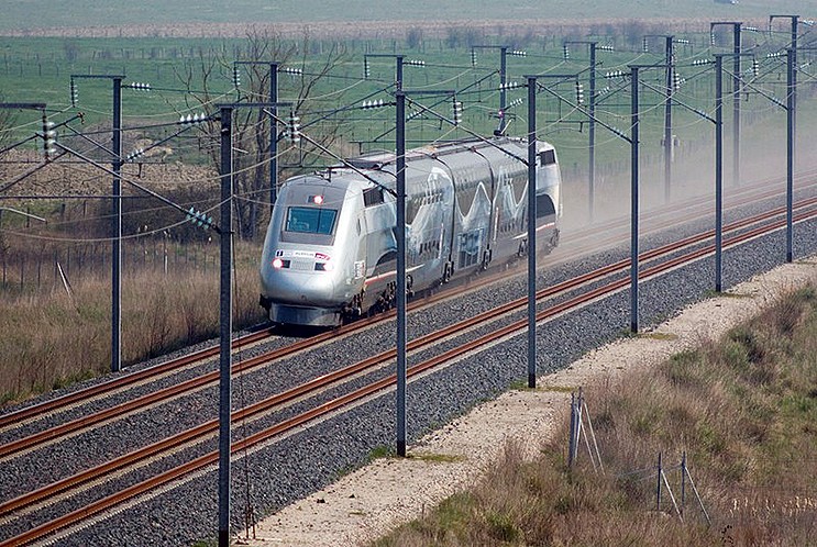
Part Four will conclude this series and focus on how the Pantograph Barrier can be eliminated and increase train speed beyond 220 MPH. In review, Part Three of this series discussed why having electrified passenger trains that can go beyond 220 MPH is important to our infrastructure and can change the way people travel. 

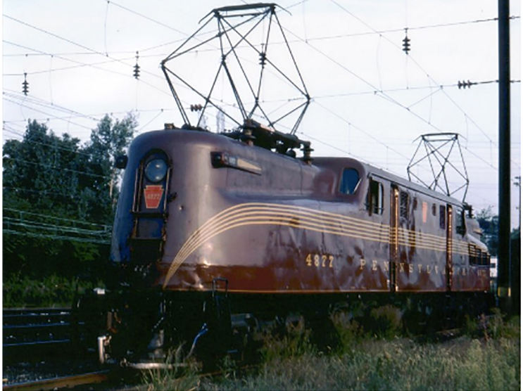
All electric trains require some system to continuously transfer large amounts of electrical current from a stationary wire (Catenary or third rail) to the moving train.  In order to get rid of the pantograph speed barriers caused by vertical displacement of the wire, a new form of the catenary is needed that will not place uneven force on the catenary wire while still allowing for the transfer of electricity. Any force on the contact wire must be balanced by an equal and opposite force.

The Balanced Force Pantograph (BFP) is a new catenary and pantograph system that contacts the wire horizontally using two sets of contacts that face each other, as opposed to the single wire contacting vertically in current systems.

The shape and tensioning system of the current catenary wire are not ideal for horizontal contact. So a new type of wire is required that has flat surfaces on both sides for the contacts to ride on.  This configuration also permits the increase in the size of the electrical contact surface and thus permitting a more consistent current transfer.

The BFP system must work with traditional pantographs as well to be commercially successful. It is not practical to build all new high-speed tracks and catenary for the exclusive use of locomotives equipped with a BFP system. In addition, it would be extraordinarily difficult to build a completely new right-of-way for 220+ MPH service. This is actually an issue that other solutions, such as the Hyperloop, have not addressed yet. In the United States, it is typical for all speeds of train service to share tracks. The BFP system must accommodate both current electric locomotives using traditional pantographs and locomotives fitted with the new BFP technology. The BFP system addresses this by making the bottom of its catenary wire curved so that it is similar to the profile of the current catenary wire and supports the use of current pantographs.

High-speed trains do not travel at top speed for many parts of their journey, because of the geometric realities of building tracks and practical limits on acceleration and deceleration. Typically, geography and congestion force train to slow down as they approach intermediate stations, interlocks, densely populated cities, and stations. The BFP is not needed at slower speeds below 200 MPH, so it only needs to be installed on sections of track that allow for 180+ MPH operations. This allows lower-speed trains using traditional pantograph technology and high-speed trains dual-equipped with current and BFPs to share tracks. The conventional catenary wire will continue to be used on sections of the track that are not suitable for high-speed operation. The BFP wire technology is designed to be retrofitted onto existing catenary systems and will permit seamless transitions from one catenary technology to the other.

Some reviewers have been skeptical that the proposed Balanced Force Pantograph and Overhead Catenary System concept can be made to work with current technology. It is possible to design and build a pantograph that can follow a wire in 3 dimensions and hold contact with the wire while traveling at 300 MPH. It will not be easy, however, tracking conventional catenary at 180 MPH and in three dimensions is already part of catenary inspections in Japan.

Other skeptics have expressed concern that the potential cost of the BFP is too high to make it feasible. The BFP system is undoubtedly more expensive to install than current catenary technology, but it allows for an increase in train operating speeds. This can have an enormous effect on the desirability of train travel and competitiveness with air travel. Building high-speed rail is already extremely expensive, and the balanced force pantograph does not significantly increase that cost. It does, however, improve the economics of high-speed rail which improves the viability of High-Speed Rail projects.

The intention of this series is to initiate a more extended discussion of the future speed of High-Speed Train Travel and to spark a discussion of the Balanced Force Pantograph system.  Increasing the possible operating speeds of trains by solving the Pantograph Barrier is part of the path to designing and building trains that can more effectively compete with air travel and other future technologies such as the Hyperloop.

Click the links below to read parts one through three of this series.

Part 1 of 4: Of Pantographs & Wires

Part 2 of 4: Effects & Consequences

Part 3 of 4: Why Speed Matters

Frank has over 45 years of diverse experience as a Professional Engineer and is registered in 17 states. His experience includes electric power generation and distribution, microwave communications, public safety radio, SCADA, fiber optic communications, and railroad communications. Currently, Frank is a Lead Consultant with MACRO, a division of Ross & Baruzzini, in Chalfont, Pennsylvania. Over the last decade and a half, he has provided consulting and engineering services to SEPTA, AMTRAK, PANYNJ, Caltrain, NJ Transit, Delaware Port Authority, San Diego Transit, and many others. In addition, he has 4 patents relating to railroad technology.

The Pantograph Barrier, Part 3 of 4: Why Speed Matters

Part One and Part Two of this series discussed the idea of a Pantograph Barrier and why it exists. Part Three will address why the pantograph barrier is significant, and why operating trains above 220 MPH is important.

Railroads were the most important form of transportation during the first few decades of the 20th Century and cities were often built around train stations. From Grand Central Station to the little town train station, they were at the center of commerce and travel. But with the rise of the automobile and the airplane, the middle of the 20th century marked the beginning of the decline of trains in North America.

Train travel is still practical and potentially profitable in a couple of use cases though. Outside of the existing North-East Corridor service that is already quite successful, there are many city-to-city trips that trains remain competitive with cars and airplanes. There are some trips that are longer than what some people want to drive but are short enough that trains can compete with airlines on time. This “sweet spot” is for trips between cities that are 300 to 600 miles apart. Driving is convenient in many ways, but it takes many hours to drive that distance. Flying is a hassle, because it may take four hours of waiting to do one hour of actual travel time. Plus not all destinations have direct flights. Passenger trains can fill this travel gap by providing quick, convenient, and relatively affordable trips in much greater comfort than flying or driving. Trips such as these are made by trains routinely in much of Europe and parts of Asia.

Of the many reasons people decide to travel by car, plane, or train, there are very few that are addressable from an engineering perspective. One area where engineering can have an impact is the speed of the train. We can reduce the travel time between cities by raising the peak cruising speed of trains. In many places, this has already been done to the maximum amount that is safe with the current track geometry, but in other places, it is possible to build a track that is capable of speeds beyond what current trains are able to do.

For example, take the California High-Speed Rail (CAHER) project. The project advertises that the travel time from Los Angeles (LA) to San Francisco (SF) will be 2 hours and 40 minutes with a top speed of 220 MPH. The project has also identified a portion of the LA to SF route as a very high-speed section. This section runs from LA to San Jose (SJ) and is about 437 miles long. The balance of the trip is on existing CalTrain tracks.

Looking at other similar rail operations the CAHER project’s advertised top speed of 220 MPH will likely turn out to be a reliable cursing speed of around 190 MPH. This discounted speed provides significant savings in catenary maintenance costs and increased reliability due to the aforementioned limitations of current catenary technology. Currently, the nonstop trip from LA to SJ will take around 2 hours and 18 minutes traveling at 190 MPH. If we can achieve a reliable cursing speed of 250 MPH (a speed that the track layout would likely allow) or 300 MPH, then the travel time drops to 1 hour and 45 minutes or 1 hour and 28 minutes respectively. This potential improvement could reduce the entire travel time from LA to SF from 2 hours and 48 minutes down to 1 hour and 58 minutes. That is a total reduction of 50 minutes. It may not seem like a lot, but the viability of the project is based on making the train a faster option than taking the plane. A downtown-to-downtown travel time of under 2 hours would make the CAHER project easily time competitive with flying.

Overcoming the Pantograph Barrier will be essential to being able to increase the speeds of electric locomotives. High speeds over 220 MPH will help facilitate trains as being a more desirable, realistic option for travelers journeying between cities that are 300 to 600 miles apart. In order to do this, current pantograph technology must be improved.

Part four of this series will introduce and discuss a possible solution to the limitations of current pantograph technology: The Balance Force Pantograph.

About the Author

Frank has over 45 years of diverse experience as a Professional Engineer and is registered in 17 states. His experience includes electric power generation and distribution, microwave communications, public safety radio, SCADA, fiber optic communications, and railroad communications. Currently, Frank is a Lead Consultant with MACRO, a division of Ross & Baruzzini, in Chalfont, Pennsylvania. Over the last decade and a half, he has provided consulting and engineering services to SEPTA, AMTRAK, PANYNJ, Caltrain, NJ Transit, Delaware Port Authority, San Diego Transit, and many others. In addition, he has 4 patents relating to railroad technology.

Salt Lake City – Gateway to Recreational Activities

Situated in the northern part of the beautiful state of Utah and next to the marvel that is the Great Salt Lake, while surrounded by the Rocky Mountains, Salt Lake City International Airport provides an access point to these marvels and more. The airport is a gateway for year-round outdoor recreational activities. In the winter months, skiers from across the country and internationally arrive at the airport, and in the summer months, mountain bike enthusiasts travel with their bikes.

Salt Lake City International Airport serves nearly 24 million customers a year and is ranked the 25th busiest in North America. Ten airlines and their affiliates service the airport which is a major hub for Delta Airlines handling about 70% of total traffic.

The Salt Lake City Terminal Redevelopment Program broke ground in 2014.  As the Designer of record for the Baggage Handling System (BHS) and Construction Administration (CA), CAGE worked closely with the City and Architects to develop a BHS with the latest technology while providing the best customer experience possible. 

The airport requested efforts be made to have the new terminal and concourses certified as a Gold Level LEED building.  CAGE assisted this effort with innovative BHS designs that included energy-saving drive systems for the conveyors and special control features for operating the conveyors in an energy-efficient manner.

Two different flight schedules – winter and summer – were analyzed to distinguish between the differing requirements and demands placed upon the BHS. 

One of the defining features of the new Baggage Handling System is the requirement that the system can convey large items such as skis and bike boxes. This means that every ticket counter and curbside baggage load point will convey these items to a security screening area, then to a suitable sort destination, and on to the appropriate aircraft.  Baggage load points include five ticket counter lines, two Gateway Center (within the parking garage) lines, two curbside lines, and one international recheck line.  The system is designed to enhance the passenger experience relative to these specific needs.

Once the baggage has been checked in, security screening will be conducted by fully in-line Explosive Detection Systems (EDS) machines.  Bags not cleared by the EDS machines will be conveyed directly to the Checked Baggage Resolution Area (CBRA) for manual inspection.

Bags cleared by the EDS machines and manual inspection are then conveyed to the South Concourse of the new terminal where the passenger gates and baggage make-up devices are located. A total of 19 make-up devices provide specific sort destinations for each flight or airline.  Large items such as bike boxes and skis will be conveyed to separate lines with specially designed baggage chutes. All bags are then collected by baggage handling personnel and placed upon carts for transport to the appropriate aircraft.

Another distinctive feature of the design includes the inbound baggage system. The inbound baggage system includes ten claim devices (eight for domestic flights and two for international) and two oversize lines with claim devices for skis and bike boxes.

Some of the technical features that are incorporated into the BHS design to meet specific requirements for the airport are:

  • Lines include 45-inch conveyors and large radius turns.
  • Special recirculating devices for loading and presenting skis.
  • Special sort destinations that can support bike boxes and skis.
  • Multiple crossover lines provide redundancy features to the BHS.
  • Innovative conveyor drive systems with new control methodologies provide excellent energy efficiencies.

CAGE is honored and excited to be a part of this project.  The new Salt Lake City Airport, when completed, will be a state-of-the-art facility and – your Gateway to the West.

Check out https://www.slcairport.com/thenewslc for more information on “The New SLC”.

About the Author

Nick Kinser is the Technical Writer for CAGE. He has accumulated over 20 years of experience in the airport baggage handling systems industry. He has previously worked for the Texas State Attorney General as a research assistant.

The Pantograph Barrier: Part 2 of 4 Effects & Consequences

Part one of this series, “Of Pantographs & Wires”, discussed the history of the electric locomotive, the evolution of catenary technology to our present day, and the idea of a Pantograph Barrier. Part two of this four-part series will examine the reasons why the Pantograph Barrier exists and its effects and consequences.

The speed of an electric locomotive is limited by several components: horsepower, the quality of the tracks, the presence of freight operations, the layout of the tracks, the signaling technology, and the Pantograph Barrier. These limitations, with the exception of the Pantograph Barrier, can be addressed by building more powerful locomotives and straighter tracks, but the Pantograph Barrier has yet to be overcome by simply improving current technology. The Pantograph Barrier is a limitation that is related to the speed of the train and the current pantograph design. The faster the train goes the worse this phenomenon becomes. Currently, the Pantograph Barrier limits the speed of electric locomotives to about 220 MPH.

The Pantograph Barrier can be examined by pushing speed limitations under controlled conditions. In 2007, the French TGV-V150 train reached a speed of 357 MPH/574.8 KM/H in non-revenue service. This pushing of the envelope was accomplished by drastically increasing the available Horsepower, increasing the traction power voltage, and, most significantly, increasing the horizontal tension on the overhead catenary beyond conventional design limits. Over the 40 or so mile-long test track, the TGV-V150 exceeded 220 MPH. However, it only pushed the Pantograph Barrier further out. It did not demonstrate a way to get past the barrier.

The barrier is integral to the way that the current pantograph interacts with the contact wire. The pantograph pushes up on the wire, typically applying between 15 and 30 pounds of force on the bottom of the wire. This force causes the wire to be vertically displaced by about 1 to 3 inches. There is a considerable body of academic literature analyzing the optimal design requirements for the wire and for the pantograph. However, there is a much smaller body of work that treats them as an interrelated set. All of this analysis confirms the simple physical reality that if you push on a wire, the wire will vibrate. When the pantograph is moving along the wire the upward pressure it exerts causes waves in the wire. The more the wire is restrained from moving the more chaotic the vibrations become. The faster the pantograph moves, the more severe the vibrations become. These vibrations damage the catenary over time and cause it to lose tension, which magnifies the problem. As we saw in the example of the TGV-V150, the vibration can be managed by increasing the horizontal force. This diminishes the amount the wire is deflected by the catenary and, by extension, limits the vibrations. But this does not resolve the underlying vibration problem.

An increasing horizontal force isn’t the only method to limit vibrations. The reduction of vertical force imparted to the wire by the pantograph is an option to reduce vibration as well. The problem is that reducing the upward force of the pantograph makes the connection between the wire and the pantograph weaker. This affects the ability of electricity to conduct and reduces the performance of the train. The top speed of a train cannot be increased without increasing horsepower. The increase in horsepower requires an increase in necessary electrical current and exacerbates the consequences of a weaker electrical connection between the pantograph and the wire. Therefore, reducing the contact force is not an attractive option. A better solution to the pantograph barrier would be to find a way to gain traction power from an overhead wire system to the locomotive. This could potentially decrease vibrations and increase the top possible speeds of electric locomotives.

Part three of this series will discuss in more detail why increasing train speeds beyond 220 MPH is important. Part four will propose a possible solution to the Pantograph Barrier problem called the Balanced Force Pantograph.

To learn more about this topic, and to get a preview of the Balanced Force Pantograph solution, attend Frank J. Smith’s presentation, “Balanced Force Pantograph and OCS” at the Joint Rail Conference in Pittsburgh, PA on April 19, 2018  

About the Contributor

Frank has over 45 years of diverse experience as a Professional Engineer and is registered in 17 states. His experience includes electric power generation and distribution, microwave communications, public safety radio, SCADA, fiber optic communications, and railroad communications. Currently, Frank is a Lead Consultant with MACRO, a division of Ross & Baruzzini, in Chalfont, Pennsylvania. Over the last decade and a half, he has provided consulting and engineering services to SEPTA, AMTRAK, PANYNJ, Caltrain, NJ Transit, Delaware Port Authority, San Diego Transit, and many others. In addition, he has 4 patents relating to railroad technology. 

The Pantograph Barrier: Part 1 of 4 Of Pantographs & Wires

The marriage of the pantograph and the catenary has been wonderfully stable and productive for 120 years, but the insurgence of high-speed trains has started to reveal a “Pantograph Barrier”. This four-part series will examine the technical issues that have caused this 120-year-old technology’s inherent limitations and how advances can lead to the operation and initiation of new, truly high-speed intercity services. Part one will begin with the history of overhead electrification technology and where the technology is today.

The first electric locomotives were put into service by the Baltimore & Ohio Railroad (B&O) in 1895 to pull trains through a tunnel under the Baltimore River, where steam engines could not venture. The B&O created the then-novel features of an electric contact wire on the tunnel ceiling and a current collection device mounted on the locomotive cab. This setup allowed trains to travel through the tunnel at speeds above 30 MPH. It would take another quarter century for the industry to see electric locomotive as an economical alternative to coal-fired locomotives. The New Haven and the Pennsylvania railroads began to install overhead electric wires and build new electric locomotives as traffic along what we now call the North East Corridor increased.

The P5a series of locomotives were the first series built by the Pennsylvania Railroad, and similar designs were then in turn built by the other railroads. This series sported diamond-shaped pantographs. Locomotive designs continued to evolve over the years as operating speeds and train weights increased. The GG1 Locomotive, also built by the Pennsylvania Railroad in the early 1940s, had a top speed of 100 MPH and was a workhorse on the rails for the next 30 years. The GG1, pictured right, is considered by many to be the pinnacle of the era of artistically designed locomotives.

Eventually, a normal operating speed of 80 MPH did not seem so impressive and the GG1s were retired in the late 70s when AMTRAK replaced them with a series of designs imported from Europe. These designs included the Z-shaped pantograph, which is the one that almost all trains in the United States use today. These new locomotives were able to pull more load and operate at over 120 MPH.

The catenary, or overhead wire, has remained essentially unchanged since its inception in the early 1900s. The wire, often called OCS (Overhead Contact System) started out as a quasi-round copper or bronze wire fixed in place over the tracks by a system of cables called a catenary. The catenary, which includes electric insulators, is supported by wayside poles, arches, or other structures. The OCS is designed to accommodate ambient temperature changes. The wire is held in place and level, but it’s not restrained from moving horizontally. The older catenary used three contact wires, but it was later reconfigured to follow the Pennsylvania Railroad convention of using one wire. Europe and Japan had to rebuild their railroads after WWII. They advanced catenary designs by placing the contact wire in a controlled horizontal tension. This design still accommodates thermally induced stretching and contraction, while allowing for higher operating speeds.

Click here to check out a video on Catenary & Pantograph: How does it work?

But catenary technology is exhibiting signs of its inherent limitations even though it has remained stable for so many years. A survey of high-speed trains the world over demonstrates that there is a Pantograph Barrier. This term was first coined by Mr. Bobillot.

In that paper, the authors conclude that we have exceeded 90% of the theoretical maximum speed of the legacy pantograph/ OCS configuration. Their conclusions are confirmed by looking at the maximum revenue operating speeds of the 10 fastest trains in Europe, Japan, and China. In general, their upper speed is about 220 MPH. This exercise is a remarkable testament to the existence of a Pantograph Barrier.  This exercise is a remarkable testament to the existence of a Pantograph Barrier. 

Part two of this series will look at the technical issues that have created the Pantograph Barrier.

If you are interested in learning more about this topic, attend Frank Smith’s presentation “Balanced Force Pantograph and OCS” at the Joint Rail Conference in Pittsburgh, PA on April 18 -20, 2018.

https://www.asme.org/events/joint-rail-conference

About the Contributor

Frank has over 45 years of diverse experience as a Professional Engineer and is registered in 17 states. His experience includes electric power generation and distribution, microwave communications, public safety radio, SCADA, fiber optic communications, and railroad communications. Currently, Frank is a Lead Consultant with MACRO, a division of Ross & Baruzzini, in Chalfont, Pennsylvania. Over the last decade and a half, he has provided consulting and engineering services to SEPTA, AMTRAK, PANYNJ, Caltrain, NJ Transit, Delaware Port Authority, San Diego Transit, and many others. In addition, he has 4 patents relating to railroad technology. 

Energy and Cost Saving Strategies for Operating Rooms

Operating rooms (ORs) are one of the most critical aspects of Hospital Operations. They must be available at all times to support critical operations and procedures. As a result, most hospital ORs operate HVAC systems 24 hours per day.

ORs are incredibly profitable when they are active, but healthcare facilities lose money when they are unused. Operating costs for ORs are susceptible to a variety of factors that affect profit such as disposable medical supplies, drug prescription waste, schedule delays, etc. But one money-saving factor is often overlooked: HVAC systems setbacks. 

ORs within healthcare facilities require a significant amount of supply air by code for infection prevention. This airflow is typically 4-5 times more than what is required to meet the temperature and humidity requirements for the space. These ORs are unused for a significant portion of a typical day for a lot of facilities. One St. Louis area hospital was recently assessed and found to only be utilizing its ORs 40% of the hours in a year. There are 8,760 hours in a year. You can do the math, but that is a lot of energy wasted. The good news is that this kind of waste can be prevented. Healthcare facilities can experience significant energy savings by reducing airflows when their ORs are unoccupied.

Reduce Airflow Using ASHRAE Standards and Local Code

ASHRAE 170 – Ventilation of Health Care Facilities is the most commonly used standard for hospital HVAC systems. This standard establishes criteria for the minimum amount of supply and ventilation air, temperature, and humidity requirements to be provided in healthcare facilities. ASHRAE 170-2017 requires ORs to be supplied with 20 Air Changes per Hour (ACH) of supply air and 4 ACH of ventilation air when occupied. These air change requirements have been reduced over time, but many hospitals are still operating at air change rates well over this requirement. In some cases, as high as 30 air changes per hour.

Airflow rates can typically be reduced by as much as 75% when the space is not occupied depending on local codes. Reducing these airflow rates will allow these facilities to achieve energy savings in

  • fan energy (reduced airflow)
  • heating energy (reheat)
  • cooling energy (air handling unit cooling coil, especially for a 100% outdoor air system)
  • humidification
  • pump energy (reduced water flow)

The opportunity to reduce airflow rates and achieve energy savings potential will vary depending on the local code requirements and the frequency that the OR rooms are used in each facility.

Airflow Setback Strategy in Action

The St. Louis area hospital mentioned above implemented an airflow reduction and setback strategy for its ORs resulting in an annual savings of $55,000 per year. This facility utilized an occupancy schedule to keep ORs fully active during normal business hours and push buttons for unoccupied period overrides. In addition to energy savings, the hospital received the added benefit of reduced maintenance and increased system life by reducing the overall demand on HVAC systems. Local utility incentives were utilized to help fund the project and the overall project paid for itself in less than 4 years.

Implementation Considerations

There are many things to consider when choosing to implement an OR airflow reduction and setback strategy.

1. Systems must have the right components to allow setbacks

The existing system must have the ability to adjust airflow rates while maintaining pressurization requirements. Air-Handling units must have variable speed supply fans; exhaust fans and return fans; and pressure-independent control of supply and return air to spaces typically using variable air volume (VAV) terminals and DDC controls.

2.  Occupancy Control Options Vary, Hospital Staff must buy-in

There are multiple ways to determine if a space is unoccupied, some options include the use of occupancy sensors, local push button controls, or both. Occupancy sensors should default to occupied mode during a sensor failure. Push button controls can be used to activate an OR for surgery or used as a local override at the nurse station. Pilot lights can be added to push buttons to provide visual notification that the OR is ready for occupancy. Proving a way for human intervention or override can provide a sense of much-needed control for the staff and flexibility during unique circumstances. Staff should be trained so there is confidence in the system.

3.  Space pressure control must be maintained

ORs must remain a positive pressure on surrounding spaces, even when unoccupied, and space pressure relationships within surrounding spaces must not be compromised by reduced airflow rates. Maintaining space pressure is not that difficult in a static (constant volume) system. It becomes more complicated in a variable volume system and space pressure balancing should be carefully thought out and reviewed.

4.  Space temperature and humidity should be maintained during setbacks

When an OR is switched to Occupied mode, the air change rate can be increased in a matter of seconds with little or no perceivable change in environmental conditions to the operating team. Temperature and humidity setpoints could take minutes or hours to recover from a setback condition. For most facilities this is unacceptable. Instead, space temperature and humidity requirements should be maintained at all times to avoid disruptions to operations.

Are Setbacks Right In Your Operating Room?

Airflow reductions and setback strategies for ORs can provide significant energy savings in healthcare facilities, especially where existing ORs operate with constant airflow, temperature, and humidity setpoints. The potential savings will vary depending on the existing system configuration and local code requirements. Hospital staff must have complete buy-in to the new system operation and receive proper training. This strategy is just one of the many ways to reduce operating costs in your operating room suite.

Learn more about how HVAC system setbacks can help your healthcare facility by contacting our team of professionals.

About the Authors

Brian Bieker, PE, LEED AP. Brian has over 20 years of experience as a mechanical engineer with a strong focus on healthcare design. Designing buildings and building systems have always been a passion for Brian and he takes pride in watching new living, breathing buildings come to life.

Ryan Walsh, PE, CEM, LEED AP BD+C. Ryan is the Director of Energy Services for Ross & Baruzzini. He has spent the last 20 years helping his customers find innovative and sustainable solutions for their most challenging and complex engineering projects including healthcare facilities.

Ross & Baruzzini Assists in Design of Global Center for Combating Extremism

World leaders, including Saudi King Salman bin Abdulaziz and President Donald Trump, inaugurated the Global Center for Combating Extremism on Sunday, May 21. The center which is headquartered in Riyadh, Saudi Arabia is “primarily focused on combating militant ideology and messaging.”

Ross & Baruzzini’s systems engineering group was instrumental in the development of innovative technologies incorporated in the center including advanced audio-visual systems, state-of-the-art-security systems and high-performance systems. These systems can monitor, process and analyze social media data/audio/video feeds with automatic simultaneous translation from multiple languages, allowing unprecedented levels of facing extremist activities in the digital world.

Click here for live footage of the inauguration and details of the construction of the facility: https://youtu.be/PhiwEndf9dY

The New Sandy Hook School – Rethinking School Security

In December of 2012, the tragic slaying of 20 children and 6 teachers at the Sandy Hook Elementary School in Newtown, CT by a lone gunman plunged our nation into grief and ignited a fierce debate over school security measures. The events in Newtown highlight a disturbing trend of armed violence in schools: since Sandy Hook, there have been 190 shooting incidents in United States schools. Proposed solutions to school gun violence include a wide spectrum of responses, ranging from increased mental health screening to the arming of teachers. 

As designers and engineers, this necessitates an important question: how can we address the need for school safety without negatively impacting the educational mission with overbearing or counterproductive security measures? Volumes have been written about school security in the last 4 years offering guidance.  Much of this literature, however, focuses on what should happen once a security event is already in progress.  The “run, hide, fight” mantra is one common refrain from security advocates.  However, this doesn’t teach us how to make sure schools are designed to withstand attacks in the first place and give police an opportunity to respond before a situation spirals out of control.

Making Sense of Tragedy

In early 2015, Sandy Hook Elementary School was demolished.  After some deliberation, Newtown officials elected to construct a new, modern school on the existing grounds.  A design team was assembled that included local architect Svigals + Partners and DVS as the security consultants and engineers. The new school promised to honor those who perished by providing a nurturing environment for generations of children to learn and flourish.

From its inception, the school design was the subject of much public curiosity. In order to help garner consensus on the direction of the design, the design team met regularly with a group of local stakeholders, including educators, town officials, board of education members, and parents of local students.  These meetings helped to move the design forward by incorporating the thoughts and ideas of those who would eventually use the school, as well as the voices of those in Newtown who was still healing from the tragedy.  The process instilled a sense of communal ownership and involvement, and would eventually become regarded as one of the key elements of the project’s success.

Designing Security

Every phase of the project design prompted meaningful dialogue on the role of security in schools. As part of the design process, our Security team convened a subcommittee consisting of town officials, first responders, and school security staff in order to evaluate all aspects of the security design as they evolved.  The focus of the group was to develop solutions that focused on preventing security events from occurring, rather than on how to deal with events in progress. These solutions ultimately influenced a wide range of design parameters, including the campus layout, school layout, construction materials, communications, and electronic security systems. The overall goal of these features was to introduce two key security elements: detection of a potential security condition before it occurred, and delay of that condition from escalating into a full-scale security event. We only needed to buy minutes of delay, the necessary window of time for on-site staff to react and law enforcement to arrive.

At each layer of the school grounds, we thought about how to introduce detection and delay.  At the campus perimeter, at the school perimeter, in general areas of the school, and at the classrooms themselves. We worked with manufacturers to test and validate new architectural materials and electronic products, incorporating some of these elements into the school design. Each of these decisions was thoroughly vetted and approved by the committee before being incorporated. 

The end result of the committee’s work was a school that was secure but did not appear imposing or restrictive. Most of the final security design elements are incorporated into the architecture of the school and are not easily visible. The school appears bright and open, with natural views and large windows into surrounding nature. As many have commented, the building is a far cry from the dark and stuffy schools of their childhood.

School Security Standardization Through Legislation

In the wake of the Sandy Hook incident, Connecticut Governor Dannel Malloy created the Sandy Hook Advisory Commission to review current state policies and make recommendations for public safety. The Commission had three areas of focus:  school safety, mental health, and gun violence protection. Our team was selected to provide input on security measures and how they can most effectively be applied in a school environment.

One key outcome of the Commission and its subsequent working committees was a report by the School Safety Infrastructure Council (SSIC), which effectively legislates minimum requirements for security for all school projects which apply for government funding. While not intended to supplant a formal security design process, the report provides a baseline for some elements of school security design, which can be incorporated as one aspect of a school’s security program. The development of the report occurred in parallel with the design of Sandy Hook School, which allowed a mutual exchange of ideas between the committee and the design team.  Upon completion of the school’s design, DVS helped develop a technical companion guide to the report, which advises architects and engineers on how to practically incorporate its requirements into design documents. 

Responses to the SSIC report have varied, but generally reflect an acknowledgment of the report as an important step forward in standardizing school security. By creating standards and tying them to state funding, it will help ensure that over time, all schools in Connecticut are brought up to a minimum level of security that is independent of size, grades served, and local demographic.

Brian P. Coulombe, PE, Principal, Director of Operations

Ross & Baruzzini Team Secures Rare Copy of the Declaration of Independence

Article was originally published on July 1, 2016. Updated on June 30, 2022.

On the night of July 4, 1776, a series of copies of the Declaration of Independence were printed by John Dunlap, which would eventually be known as the “Dunlap Broadsides.”  Of these copies, 26 are known to be in existence today. Ross & Baruzzini’s Security team has provided security for six of the Dunlap Broadsides, including the ones at Independence National Park, the Morgan Library, Massachusetts Historical Society, and Princeton University.  The copy of the Declaration of Independence that was signed by Congress is known as the “engrossed” or “parchment” copy and is currently housed in the National Archives in Washington, D.C.

Our Security team was appointed security consultant and engineer for the Olin Library at Washington University in St. Louis, where another copy of the Declaration is set to become the centerpiece of a new exhibit.  Our team designed all of the electronic security systems for the space, including video surveillance, access control, and intrusion detection. Working with the designers of the Declaration’s custom casework, we are currently investigating a number of cutting-edge technologies to help preserve and protect the document, helping to ensure it will remain viable and on display for future generations to appreciate.

For more information, and to watch a video produced by Washington University, click here for an article from the St. Louis Business Journal.

See Forever: The opening of the World Trade Center Observation Deck

DVS, a former division of Ross & Baruzzini, helped open the One World Observatory, the Observation Deck located at the top of One World Trade Center. The event was a capstone to more than a decade of work on the 1,776-foot tall building, which anchors the rebuilt World Trade Center and a revamped lower Manhattan skyline.

DVS and the World Trade Center:  A 13-Year Legacy

DVS has been a part of the design and construction effort at the new World Trade Center in New York since as early as 2002 when a team was assembled to begin work on Tower 7, a comparatively modest 52-story  building located just off of the north side of the site. Since then, DVS has been involved in providing security consulting and engineering services across many aspects of the 16-acre World Trade Center plot, including Towers 1, 2, 3, 4, 7, the PATH Transportation Hub, the Memorial, and St. Nicholas Church. DVS has also been engaged in a number of site-wide security initiatives aimed at holistically securing the site both during construction and its steady-state full occupancy.

When the Memorial opened on the 10-year anniversary of 9/11, we were stationed in the site-wide Security Operations Center with the Secret Service, who were using many of the systems that DVS had designed. When Navy Seals killed Osama Bin Laden in 2011, DVS was there as the One World Trade Center construction workers spent an entire night changing all of the construction lights to red, white, and blue – an effect that made the unfinished tower look like a giant Astro-Pop emerging from the construction site.

In many ways, the road hasn’t been easy. Developing security protocols for the site has been a difficult task involving numerous stakeholders: the City, NYPD, FDNY, the Port Authority of NY & NJ, Silverstein Properties, architects, engineers, and consultants. Battles over budgets, schedules, constructability, and the Great Recession have compounded the complexity of the task.  Our tenure has seen countless firms and talented designers come and go. Lasting relationships have been forged under immense pressure to complete the work at hand. Through it all, we have toiled on, and over the past few years, we have seen years of hard work spring to life as skyscrapers have been topped, plazas were opened, and tourists have returned in droves to see the resurgence of downtown New York.

One World Trade Center: A Decade to Reach 1,776 Feet

DVS began work on One World Trade Center (originally called the “Freedom Tower”) back in 2005 as the security consultant and engineer of record for the electronic security system. This involved careful evaluation of almost every aspect of the building’s design and function: structural robustness, façade, floor plan layouts, mechanical and electrical systems, fire detection and suppression, emergency evacuation, vertical transportation, video surveillance, access control, and IT.  All of these systems were designed with the mindset of increasing the resiliency and response capabilities of the building.

In 2013, with the completion of its iconic spire, One World Trade Center surpassed the Willis (Sears) Tower in Chicago as the tallest building in the Western Hemisphere. In a deliberate nod to the year the Declaration of Independence was signed, the building now stands at 1,776 feet, towering over the World Trade Center site and the rest of lower Manhattan.

The One World Observatory

DVS began work on the Observation Deck at One World Trade Center in 2013.  The facility, officially dubbed the “One World Observatory,” is operated by Legends Hospitality, an organization created by the Dallas Cowboys and New York Yankees in 2008 with the mission of providing world-class entertainment venues. The Observatory occupies the 100-102nd Floors with an entry and screening area on the first below-grade level of the building.

DVS was retained to provide security consulting and engineering services for the facility. This included adapting the base building security protocols to fit the function and operations of the Observatory while marrying a number of Observatory and base building electronic systems. The most challenging aspect was ensuring the visitor screening facility was designed to accommodate the millions of annual guests expected to visit. This involved evaluating a number of cutting-edge screening technologies and collecting screening throughput data from similar facilities.

On May 16, 2015, as construction on the facility was completed, DVS was invited to participate in Project Team Appreciation Day which allowed DVS team members and their families to visit the Observatory. This special event provided guests full access to the facility, including the entry lobby and “Foundations” exhibit, the See Forever Theater, and all three levels of the Observation Deck. Despite clouds in the forecast, the view from the Observation Deck remained breathtaking.

It was a great day for DVS, Legends, and the entire World Trade Center community. To see the Observatory come to life after years of hard work is a tribute to the design team, the operations, and the ownership group and to the resiliency of lower Manhattan. Without a doubt, the Observatory will be a major attraction for downtown New York for many years to come and will help continue to spur the incredible resurgence that is taking place there.

For those of us who have been around for a decade or longer of work on the World Trade Center site, the event held an even deeper significance.  It was a day to reflect on the dramatic transformation of the site and the many years of hard work that it has taken to get there. The walk back to the nearby DVS project office afterward highlighted another important observation: crowds of tourists clogged the streets, Memorial plaza, newly opened shops, stores, and transit facilities. Lower Manhattan is back with a vengeance.

About the Author:

Brian Coulombe, PE, is a Principal with DVS specializing in the design and implementation of low voltage systems, fiber optic transmission systems, and secure Ethernet networks. For the past nine years, Brian has served as the project manager for the electronic security systems design and implementation at the World Trade Center site in New York and is also serving as the project manager for the security design and implementation at several other high-profile projects, including Skyrise Miami, Sandy Hook Elementary School, and Manhattan West. Brian holds a BS in Electrical Engineering from Lehigh University and an MBA from Yale University.

DVS was acquired by Introba (formerly Ross & Baruzzini) in January and is one of the oldest and most trusted independent security consulting and engineering firms in the United States. DVS has provided risk and protection consulting services since 1964.  For more information visit www.dvssecurity.com