Ross & Baruzzini is pleased to announce its ranking at No. 278 on Engineering News-Record’s (ENR) annual list of the Top 500 Design Firms. This position is up from the firm’s 2017 ranking of No. 309 and is the eighth consecutive year that Ross & Baruzzini has been recognized as a Top 500 Design Firm.
ENR, a respected publication in the architecture, engineering, and construction industry, publishes its nationwide Top Design Firm list annually. Published annually in April, the list ranks the 500 largest U.S.-based designs firms, both publicly and privately held, based on design-specific revenue.
Part One and Part Two of this series discussed the idea of a Pantograph Barrier and why it exists. Part Three will address why the pantograph barrier is significant, and why operating trains above 220 MPH is important.
Railroads were the most important form of transportation during the first few decades of the 20th Century and cities were often built around train stations. From Grand Central Station to the little town train station, they were at the center of commerce and travel. But with the rise of the automobile and the airplane, the middle of the 20th century marked the beginning of the decline of trains in North America.
Train travel is still practical and potentially profitable in a couple of use cases though. Outside of the existing North-East Corridor service that is already quite successful, there are many city-to-city trips that trains remain competitive with cars and airplanes. There are some trips that are longer than what some people want to drive but are short enough that trains can compete with airlines on time. This “sweet spot” is for trips between cities that are 300 to 600 miles apart. Driving is convenient in many ways, but it takes many hours to drive that distance. Flying is a hassle, because it may take four hours of waiting to do one hour of actual travel time. Plus not all destinations have direct flights. Passenger trains can fill this travel gap by providing quick, convenient, and relatively affordable trips in much greater comfort than flying or driving. Trips such as these are made by trains routinely in much of Europe and parts of Asia.
Of the many reasons people decide to travel by car, plane, or train, there are very few that are addressable from an engineering perspective. One area where engineering can have an impact is the speed of the train. We can reduce the travel time between cities by raising the peak cruising speed of trains. In many places, this has already been done to the maximum amount that is safe with the current track geometry, but in other places, it is possible to build a track that is capable of speeds beyond what current trains are able to do.
For example, take the California High-Speed Rail (CAHER) project. The project advertises that the travel time from Los Angeles (LA) to San Francisco (SF) will be 2 hours and 40 minutes with a top speed of 220 MPH. The project has also identified a portion of the LA to SF route as a very high-speed section. This section runs from LA to San Jose (SJ) and is about 437 miles long. The balance of the trip is on existing CalTrain tracks.
Looking at other similar rail operations the CAHER project’s advertised top speed of 220 MPH will likely turn out to be a reliable cursing speed of around 190 MPH. This discounted speed provides significant savings in catenary maintenance costs and increased reliability due to the aforementioned limitations of current catenary technology. Currently, the nonstop trip from LA to SJ will take around 2 hours and 18 minutes traveling at 190 MPH. If we can achieve a reliable cursing speed of 250 MPH (a speed that the track layout would likely allow) or 300 MPH, then the travel time drops to 1 hour and 45 minutes or 1 hour and 28 minutes respectively. This potential improvement could reduce the entire travel time from LA to SF from 2 hours and 48 minutes down to 1 hour and 58 minutes. That is a total reduction of 50 minutes. It may not seem like a lot, but the viability of the project is based on making the train a faster option than taking the plane. A downtown-to-downtown travel time of under 2 hours would make the CAHER project easily time competitive with flying.
Overcoming the Pantograph Barrier will be essential to being able to increase the speeds of electric locomotives. High speeds over 220 MPH will help facilitate trains as being a more desirable, realistic option for travelers journeying between cities that are 300 to 600 miles apart. In order to do this, current pantograph technology must be improved.
Part four of this series will introduce and discuss a possible solution to the limitations of current pantograph technology: The Balance Force Pantograph.
About the Author
Frank has over 45 years of diverse experience as a Professional Engineer and is registered in 17 states. His experience includes electric power generation and distribution, microwave communications, public safety radio, SCADA, fiber optic communications, and railroad communications. Currently, Frank is a Lead Consultant with MACRO, a division of Ross & Baruzzini, in Chalfont, Pennsylvania. Over the last decade and a half, he has provided consulting and engineering services to SEPTA, AMTRAK, PANYNJ, Caltrain, NJ Transit, Delaware Port Authority, San Diego Transit, and many others. In addition, he has 4 patents relating to railroad technology.
Situated in the northern part of the beautiful state of Utah and next to the marvel that is the Great Salt Lake, while surrounded by the Rocky Mountains, Salt Lake City International Airport provides an access point to these marvels and more. The airport is a gateway for year-round outdoor recreational activities. In the winter months, skiers from across the country and internationally arrive at the airport, and in the summer months, mountain bike enthusiasts travel with their bikes.
Salt Lake City International Airport serves nearly 24 million customers a year and is ranked the 25th busiest in North America. Ten airlines and their affiliates service the airport which is a major hub for Delta Airlines handling about 70% of total traffic.
The Salt Lake City Terminal Redevelopment Program broke ground in 2014. As the Designer of record for the Baggage Handling System (BHS) and Construction Administration (CA), CAGE worked closely with the City and Architects to develop a BHS with the latest technology while providing the best customer experience possible.
The airport requested efforts be made to have the new terminal and concourses certified as a Gold Level LEED building. CAGE assisted this effort with innovative BHS designs that included energy-saving drive systems for the conveyors and special control features for operating the conveyors in an energy-efficient manner.
Two different flight schedules – winter and summer – were analyzed to distinguish between the differing requirements and demands placed upon the BHS.
One of the defining features of the new Baggage Handling System is the requirement that the system can convey large items such as skis and bike boxes. This means that every ticket counter and curbside baggage load point will convey these items to a security screening area, then to a suitable sort destination, and on to the appropriate aircraft. Baggage load points include five ticket counter lines, two Gateway Center (within the parking garage) lines, two curbside lines, and one international recheck line. The system is designed to enhance the passenger experience relative to these specific needs.
Once the baggage has been checked in, security screening will be conducted by fully in-line Explosive Detection Systems (EDS) machines. Bags not cleared by the EDS machines will be conveyed directly to the Checked Baggage Resolution Area (CBRA) for manual inspection.
Bags cleared by the EDS machines and manual inspection are then conveyed to the South Concourse of the new terminal where the passenger gates and baggage make-up devices are located. A total of 19 make-up devices provide specific sort destinations for each flight or airline. Large items such as bike boxes and skis will be conveyed to separate lines with specially designed baggage chutes. All bags are then collected by baggage handling personnel and placed upon carts for transport to the appropriate aircraft.
Another distinctive feature of the design includes the inbound baggage system. The inbound baggage system includes ten claim devices (eight for domestic flights and two for international) and two oversize lines with claim devices for skis and bike boxes.
Some of the technical features that are incorporated into the BHS design to meet specific requirements for the airport are:
Lines include 45-inch conveyors and large radius turns.
Special recirculating devices for loading and presenting skis.
Special sort destinations that can support bike boxes and skis.
Multiple crossover lines provide redundancy features to the BHS.
Innovative conveyor drive systems with new control methodologies provide excellent energy efficiencies.
CAGE is honored and excited to be a part of this project. The new Salt Lake City Airport, when completed, will be a state-of-the-art facility and – your Gateway to the West.
Nick Kinser is the Technical Writer for CAGE. He has accumulated over 20 years of experience in the airport baggage handling systems industry. He has previously worked for the Texas State Attorney General as a research assistant.
Part one of this series, “Of Pantographs & Wires”, discussed the history of the electric locomotive, the evolution of catenary technology to our present day, and the idea of a Pantograph Barrier. Part two of this four-part series will examine the reasons why the Pantograph Barrier exists and its effects and consequences.
The speed of an electric locomotive is limited by several components: horsepower, the quality of the tracks, the presence of freight operations, the layout of the tracks, the signaling technology, and the Pantograph Barrier. These limitations, with the exception of the Pantograph Barrier, can be addressed by building more powerful locomotives and straighter tracks, but the Pantograph Barrier has yet to be overcome by simply improving current technology. The Pantograph Barrier is a limitation that is related to the speed of the train and the current pantograph design. The faster the train goes the worse this phenomenon becomes. Currently, the Pantograph Barrier limits the speed of electric locomotives to about 220 MPH.
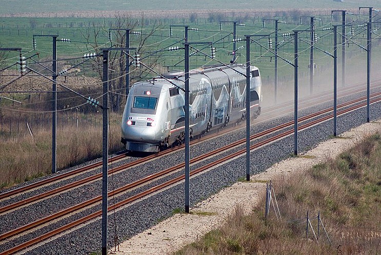
The Pantograph Barrier can be examined by pushing speed limitations under controlled conditions. In 2007, the French TGV-V150 train reached a speed of 357 MPH/574.8 KM/H in non-revenue service. This pushing of the envelope was accomplished by drastically increasing the available Horsepower, increasing the traction power voltage, and, most significantly, increasing the horizontal tension on the overhead catenary beyond conventional design limits. Over the 40 or so mile-long test track, the TGV-V150 exceeded 220 MPH. However, it only pushed the Pantograph Barrier further out. It did not demonstrate a way to get past the barrier.
The barrier is integral to the way that the current pantograph interacts with the contact wire. The pantograph pushes up on the wire, typically applying between 15 and 30 pounds of force on the bottom of the wire. This force causes the wire to be vertically displaced by about 1 to 3 inches. There is a considerable body of academic literature analyzing the optimal design requirements for the wire and for the pantograph. However, there is a much smaller body of work that treats them as an interrelated set. All of this analysis confirms the simple physical reality that if you push on a wire, the wire will vibrate. When the pantograph is moving along the wire the upward pressure it exerts causes waves in the wire. The more the wire is restrained from moving the more chaotic the vibrations become. The faster the pantograph moves, the more severe the vibrations become. These vibrations damage the catenary over time and cause it to lose tension, which magnifies the problem. As we saw in the example of the TGV-V150, the vibration can be managed by increasing the horizontal force. This diminishes the amount the wire is deflected by the catenary and, by extension, limits the vibrations. But this does not resolve the underlying vibration problem.
An increasing horizontal force isn’t the only method to limit vibrations. The reduction of vertical force imparted to the wire by the pantograph is an option to reduce vibration as well. The problem is that reducing the upward force of the pantograph makes the connection between the wire and the pantograph weaker. This affects the ability of electricity to conduct and reduces the performance of the train. The top speed of a train cannot be increased without increasing horsepower. The increase in horsepower requires an increase in necessary electrical current and exacerbates the consequences of a weaker electrical connection between the pantograph and the wire. Therefore, reducing the contact force is not an attractive option. A better solution to the pantograph barrier would be to find a way to gain traction power from an overhead wire system to the locomotive. This could potentially decrease vibrations and increase the top possible speeds of electric locomotives.
Part three of this series will discuss in more detail why increasing train speeds beyond 220 MPH is important. Part four will propose a possible solution to the Pantograph Barrier problem called the Balanced Force Pantograph.
To learn more about this topic, and to get a preview of the Balanced Force Pantograph solution, attend Frank J. Smith’s presentation, “Balanced Force Pantograph and OCS” at theJoint Rail Conference in Pittsburgh, PA on April 19, 2018
About the Contributor
Frank has over 45 years of diverse experience as a Professional Engineer and is registered in 17 states. His experience includes electric power generation and distribution, microwave communications, public safety radio, SCADA, fiber optic communications, and railroad communications. Currently, Frank is a Lead Consultant with MACRO, a division of Ross & Baruzzini, in Chalfont, Pennsylvania. Over the last decade and a half, he has provided consulting and engineering services to SEPTA, AMTRAK, PANYNJ, Caltrain, NJ Transit, Delaware Port Authority, San Diego Transit, and many others. In addition, he has 4 patents relating to railroad technology.
The marriage of the pantograph and the catenary has been wonderfully stable and productive for 120 years, but the insurgence of high-speed trains has started to reveal a “Pantograph Barrier”. This four-part series will examine the technical issues that have caused this 120-year-old technology’s inherent limitations and how advances can lead to the operation and initiation of new, truly high-speed intercity services. Part one will begin with the history of overhead electrification technology and where the technology is today.
The first electric locomotives were put into service by the Baltimore & Ohio Railroad (B&O) in 1895 to pull trains through a tunnel under the Baltimore River, where steam engines could not venture. The B&O created the then-novel features of an electric contact wire on the tunnel ceiling and a current collection device mounted on the locomotive cab. This setup allowed trains to travel through the tunnel at speeds above 30 MPH. It would take another quarter century for the industry to see electric locomotive as an economical alternative to coal-fired locomotives. The New Haven and the Pennsylvania railroads began to install overhead electric wires and build new electric locomotives as traffic along what we now call the North East Corridor increased.
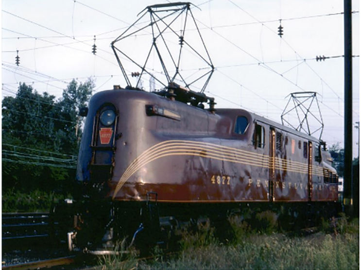
The P5a series of locomotives were the first series built by the Pennsylvania Railroad, and similar designs were then in turn built by the other railroads. This series sported diamond-shaped pantographs. Locomotive designs continued to evolve over the years as operating speeds and train weights increased. The GG1 Locomotive, also built by the Pennsylvania Railroad in the early 1940s, had a top speed of 100 MPH and was a workhorse on the rails for the next 30 years. The GG1, pictured right, is considered by many to be the pinnacle of the era of artistically designed locomotives.
Eventually, a normal operating speed of 80 MPH did not seem so impressive and the GG1s were retired in the late 70s when AMTRAK replaced them with a series of designs imported from Europe. These designs included the Z-shaped pantograph, which is the one that almost all trains in the United States use today. These new locomotives were able to pull more load and operate at over 120 MPH.
The catenary, or overhead wire, has remained essentially unchanged since its inception in the early 1900s. The wire, often called OCS (Overhead Contact System) started out as a quasi-round copper or bronze wire fixed in place over the tracks by a system of cables called a catenary. The catenary, which includes electric insulators, is supported by wayside poles, arches, or other structures. The OCS is designed to accommodate ambient temperature changes. The wire is held in place and level, but it’s not restrained from moving horizontally. The older catenary used three contact wires, but it was later reconfigured to follow the Pennsylvania Railroad convention of using one wire. Europe and Japan had to rebuild their railroads after WWII. They advanced catenary designs by placing the contact wire in a controlled horizontal tension. This design still accommodates thermally induced stretching and contraction, while allowing for higher operating speeds.
But catenary technology is exhibiting signs of its inherent limitations even though it has remained stable for so many years. A survey of high-speed trains the world over demonstrates that there is a Pantograph Barrier. This term was first coined by Mr. Bobillot.
In that paper, the authors conclude that we have exceeded 90% of the theoretical maximum speed of the legacy pantograph/ OCS configuration. Their conclusions are confirmed by looking at the maximum revenue operating speeds of the 10 fastest trains in Europe, Japan, and China. In general, their upper speed is about 220 MPH. This exercise is a remarkable testament to the existence of a Pantograph Barrier. This exercise is a remarkable testament to the existence of a Pantograph Barrier.
Part two of this series will look at the technical issues that have created the Pantograph Barrier.
If you are interested in learning more about this topic, attend Frank Smith’s presentation “Balanced Force Pantograph and OCS” at the Joint Rail Conference in Pittsburgh, PA on April 18 -20, 2018.
Frank has over 45 years of diverse experience as a Professional Engineer and is registered in 17 states. His experience includes electric power generation and distribution, microwave communications, public safety radio, SCADA, fiber optic communications, and railroad communications. Currently, Frank is a Lead Consultant with MACRO, a division of Ross & Baruzzini, in Chalfont, Pennsylvania. Over the last decade and a half, he has provided consulting and engineering services to SEPTA, AMTRAK, PANYNJ, Caltrain, NJ Transit, Delaware Port Authority, San Diego Transit, and many others. In addition, he has 4 patents relating to railroad technology.
Facility Operator involvement during the early conceptual development stage of the design process can have the greatest impact on the project’s ultimate success. The Operators understand their facility better than anyone else and the results of the project will directly affect them. Therefore, their input can be very valuable to the Design Team.
Facility Operators are the primary users of all of the systems in a facility and are typically responsible for making sure these systems work together to achieve the desired results of the facility. They must know the “how” and “why” of each system to be able to use them effectively.
There are several key discussions the Design Team should engage Facility Operators in to help ensure the success of a project.
Current Operations and Methods of Execution
Facility Operators are the best resource available to the Design Team to gain an understanding of how a facility needs to operate and what characteristics of the existing facility could be improved. Their intimate knowledge of the current operations of the facility and what methods they utilize can provide the Design Team with valuable insights.
Improvements Wish List
The design process can be enhanced by asking the Facility Operators what desired improvements they would like to see implemented into the facility. It is much easier to incorporate their needs into the project scope if the Design Team can involve the operators in a collaborative effort very early in the design. It is also important to work closely with the Owner/Client in this collaboration to formulate the project goals and establish the project budget and schedule.
Potential Roadblocks
Roadblocks to effective implementation of project goals are often encountered throughout a project design. These roadblocks might range from physical constraints of the facility to attitudes displayed by various individuals. The collaboration with the Facility Operators can help uncover these roadblocks early in the process so they can be more effectively addressed.
Extended Facility Operations Involvement
The Design Team, by necessity, will assume the lion’s share of the work as the project moves into the design development and its detailed implementation. Even though the Design Team owns the majority of responsibility at this stage, it is important to continue to solicit input from the Facility Operators throughout the process.
Mini-reviews during the design of a project are often more effective than one or two major ones. This is especially true for facilities that are driven by technical process requirements like those in Water and Wastewater facilities. Keeping a consistent review team that includes the Facility Operators will make minor modifications and corrections easier to accomplish.
It is also critical to involve the Facility Operators during the final stage of a project when the facility is being turned over and the final documentation is presented to the Owner. During this time the Facility Operators need to receive their training in the use and ongoing maintenance of their new facility. They should also be included in the team that checks out the final facility to certify that their expectations have been met.
A project’s success can be amplified when the Design Team collaborates with the Facility Operators and treats them as an integral resource. Their value cannot be emphasized enough. They know their facility better than anyone else and will have to live with the results of the project.
Bob Wilson has over 42 years of experience in controls, instrumentation, security, standby generation, and power distribution. He has spent 21 of those years with Ross & Baruzzini serving in the roles of senior engineer and project manager. Bob holds a B.S. in Electrical Engineering from the University of Oklahoma and is a registered professional engineer. In addition to his long-time emphasis on projects in the Water and Wastewater industries, he has led and participated in many projects for the manufacturing, packaging, and process chemical industries as well as healthcare and transportation.